

降低摩擦阻力可以有效提高飞机的经济效益,降低能源消耗。相关研究表明,飞机飞行过程中的摩擦阻力占总阻力的40%~50%[1]。减小摩擦阻力的方式有很多种,如表面活性剂减阻、微气泡减阻、超疏水涂层减阻和微结构减阻等。其中微结构减阻来源于仿生学,并以能源消耗率低、易加工的优势被广泛应用于交通运输、风机叶片、船舶、航空航天等领域。
国内外学者对沟槽结构减阻特性进行了大量的研究。Jiang等[2]提出了一种类似沙丘的微观结构,研究结果表明,微结构表面可有效减小摩擦阻力。Yan等[3]发现仿生鱼鳞表面总减阻率为35.15%,升阻比提高18.04%。Zhang等[4]受鳗鱼皮启发,开发了一种高减阻性能的仿生涂层,减阻率可达18.7%。Qu等[5]开发了一种基于鲨鱼皮肤微观结构和超疏水涂层的减阻表面,减阻率达66.57%。Fan等[6]受鲨鱼皮启发,设计了两种罗纹表面,模拟结果表明,减阻率为21.45%。Wang等[7]指出扇形肋骨与三角形肋骨相比具有更高的减阻率,扇形肋骨的减阻率达7.8%。Liu等[8]对带有流向沟槽结构的机翼表面进行了仿真分析,结果表明,减阻率为14.5%。Nguyen等[9] 研究了纵向沟槽对不同锥形船尾模型阻力的影响,结果表明,带沟槽结构可以减小高达24%的流动阻力。Wang等[10]对布置流向凹槽的矩形通道进行了仿真分析,结果表明,流向沟槽减阻率达11.7%~16.78%。姜洪鹏等[11]发现经过疏水处理后的刀刃形和锯齿形沟槽减阻率显著提升,分别由9.52%和13.70%增加到58.00%和63.00%。李永成等[12]对V形、U形和L形沟槽的减阻效果进行了对比分析,结果表明,V形沟槽的减阻效果最优。牛志罡等[13]发现 L形纵向沟槽比V形具有更好的减阻效果,最大减阻率为5.60%。徐琰等[14]研究了不同尺寸的三角形沟槽减阻效果,经分析,在来流速度为25 m/s时,沟槽宽度为0.3 mm,沟槽深度为0.2 mm的沟槽结构减阻效果最佳。刘朝阳等[15]发现,超疏水微沟槽壁面的减阻率为13.80%,而超疏水微凸柱壁面的减阻率仅为10.20%。黄明吉等[16]分析了仿生微结构对离心泵叶片表面阻力的影响,结果表明,流向布置的矩形沟槽减阻效果最好,最大减阻率为8.39%。杜淑雅等[17]通过大涡模拟研究了横向三角形与梯形沟槽的减阻特性,结果表明,梯形沟槽的减阻效果优于三角形。
以上文献主要针对不同形状和尺寸纵向或横向的沟槽模型进行减阻分析,但并没有同时分析纵、横向沟槽减阻特性。本文在前人研究的基础上,对二维横向、三维横向和三维纵向沟槽模型进行了仿真研究,选取不同尺寸的三角形和梯形沟槽为研究对象,分析不同尺寸、不同来流方向和不同速度对减阻效果的影响。
1 湍流模型
本文所选流体为不可压缩空气,计算域流体密度ρ为1.225 kg/m3,动力黏度μ为1.789×105 N·s/m2。
减阻率为光滑表面阻力系数与沟槽表面阻力系数的差值占光滑表面阻力系数的百分比,其表达式为
式中: 为光滑表面阻力系数; 为沟槽表面阻力系数。
2 模型建立及网格划分
2.1 模型建立
本文对不同尺寸的三角形和梯形沟槽进行仿真,验证其减阻特性,确定最优减阻尺寸。平板模型要保证湍流充分流动,因此计算域流向长度设为200 mm、上下平板间距为15 mm、展向长度为10 mm,如图1所示。入口边界条件设置为速度进口,出口边界条件设置为压力出口,两侧壁面设置为对称面。在10~60 m/s的速度下进行仿真计算。

表1 三角形沟槽尺寸 (mm) |
| 沟槽深度h | 沟槽宽度s |
|---|---|
| 0.1 | 0.10 |
| 0.1 | 0.15 |
| 0.1 | 0.20 |
| 0.1 | 0.25 |
| 0.1 | 0.30 |
表2 梯形沟槽尺寸 (mm) |
| 沟槽深度 h | 沟槽长底边 宽度s | 沟槽短底边 宽度s 1 |
|---|---|---|
| 0.1 | 0.10 | 0.02 |
| 0.1 | 0.15 | 0.03 |
| 0.1 | 0.20 | 0.04 |
| 0.1 | 0.25 | 0.05 |
| 0.1 | 0.30 | 0.06 |
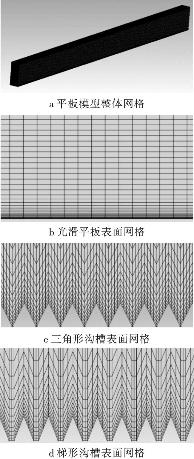
2.2 网格划分
计算域采用结构网格划分,对沟槽处网格进行加密,距离沟槽较远的远场流域网格数量可适当减少,以缩短计算时间,减小计算量,平板模型网格划分如图2所示。
2.3 网格无关性验证
3 仿真结果分析
3.1 减阻机理

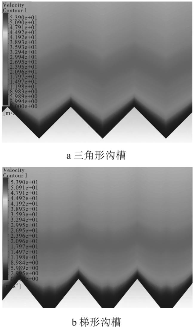
3.2 速度云图分析
宽s为0.2 mm、深h为0.1 mm的三角形和梯形沟槽表面的速度云图如图5所示。由于摩擦阻力的阻滞作用,在三角形与梯形沟槽内部均存在低速流体,形成低速区,使原有的流固交界面变为流流交界面,进一步减小了摩擦阻力。对于不同形状沟槽,梯形沟槽的低速流体区域大于三角形沟槽,可以更好地“锁住”低速流体,减阻效果更好。
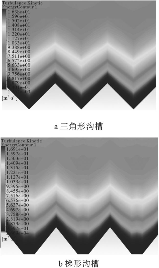
3.3 湍流动能云图分析
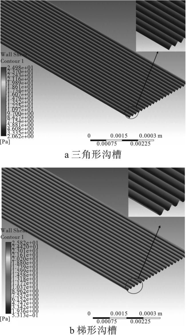
3.4 剪切应力云图分析
4 减阻率对比
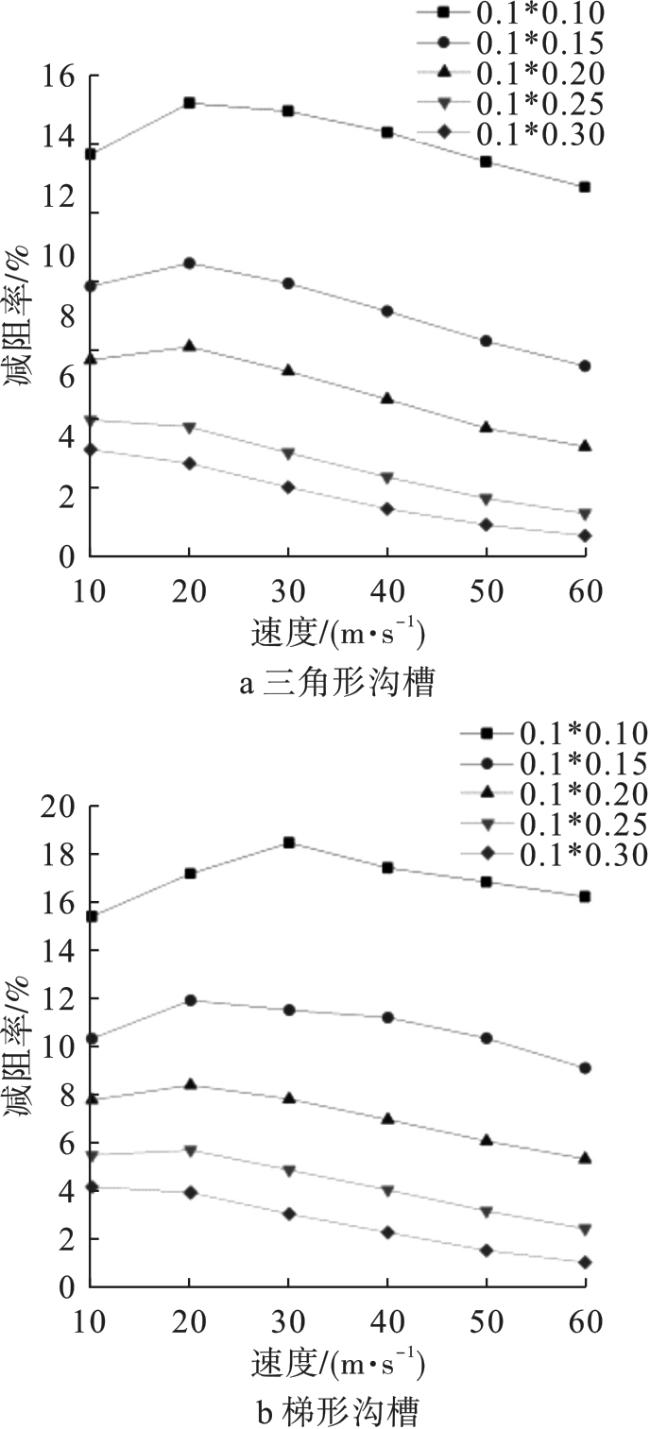
4.1 纵向沟槽表面减阻率
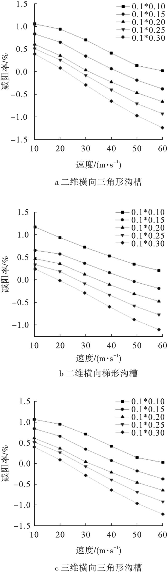
4.2 横向沟槽减阻率
5 结论
本文以三角形和梯形沟槽为研究对象,通过数值模拟分析不同来流方向、宽深比和来流速度对减阻效果的影响,得到如下结论:
1)横向沟槽的内部流体可以起到“滚动轴承”的作用,将原有的滑动摩擦变为了滚动摩擦,减小阻力。而纵向沟槽则是在流体流过沟槽表面时,由于阻力的影响,在沟槽内部产生低速流体,使得近壁面速度梯度减小,达到减阻效果。
2)通过对三角形和梯形沟槽模型的仿真对比分析发现,在沟槽底部均存在低速流体,这些低速流体使得近壁面流固交界面变为流流交界面,减小了摩擦阻力,在沟槽底部湍流强度和剪切应力也较小,说明沟槽结构可以有效降低能量损耗并减小黏性阻力。
3)二维横向、三维横向和三维纵向三角形与梯形沟槽结构的减阻率的对比表明,二维横向与三维横向沟槽结构的减阻率相近,纵向沟槽结构的减阻率高于横向沟槽,且梯形沟槽的减阻率高于三角形沟槽。减阻率随着沟槽宽深比和速度的增大,均呈现减小趋势,在沟槽宽s为0.1 mm、深h为0.1 mm时,减阻率取得最大值,最大减阻率为18.57%。